Beeping Bela
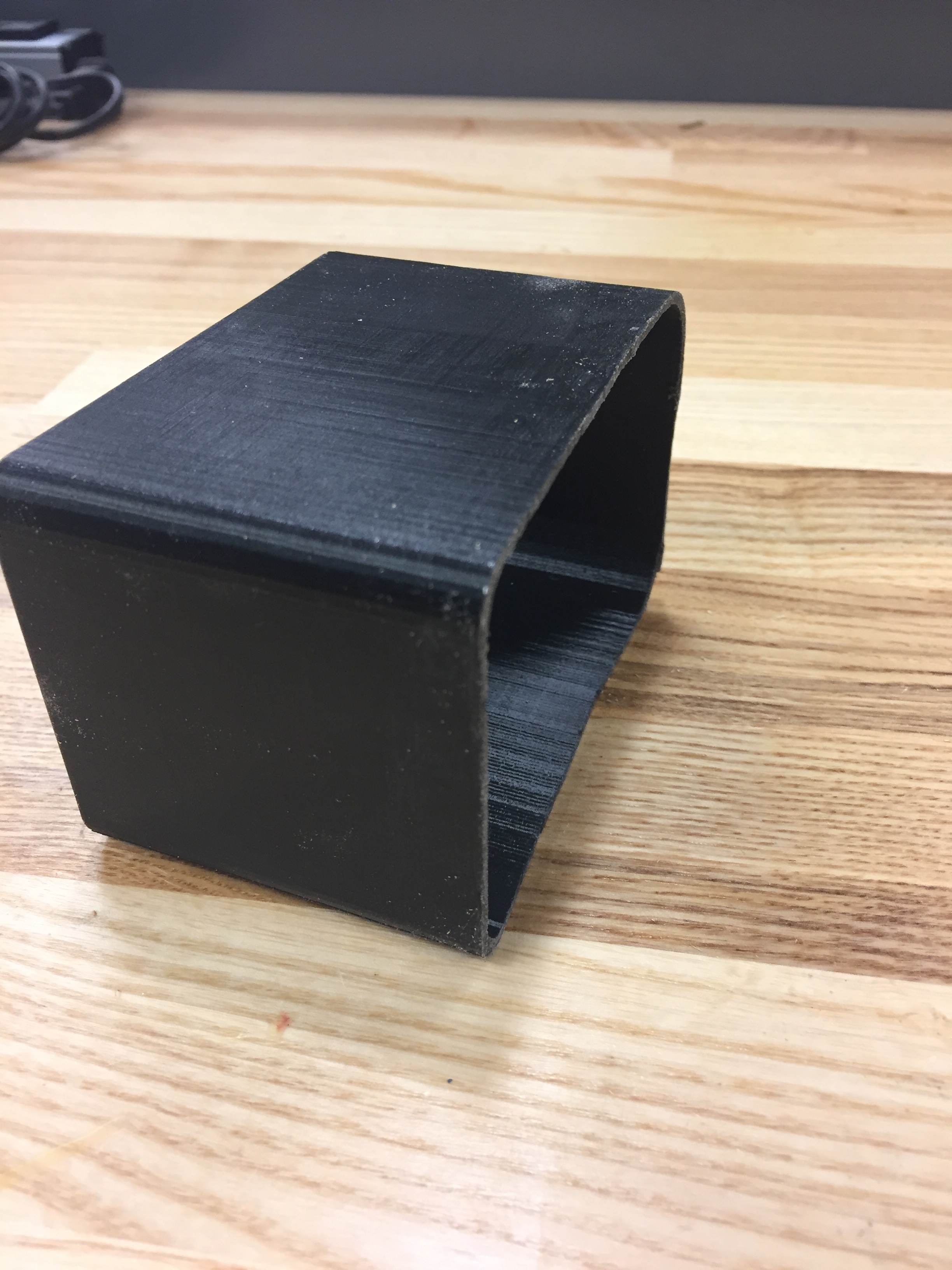
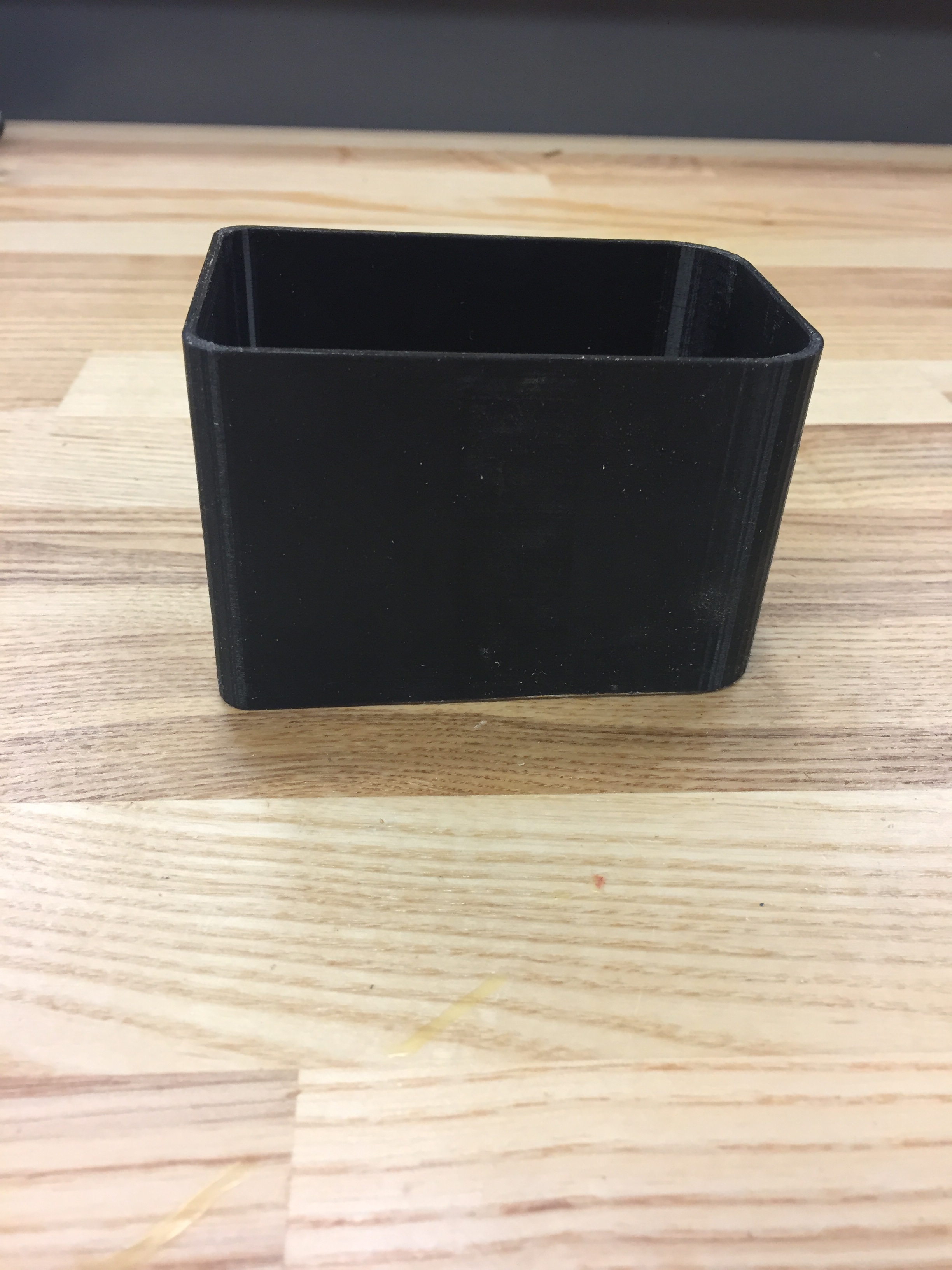
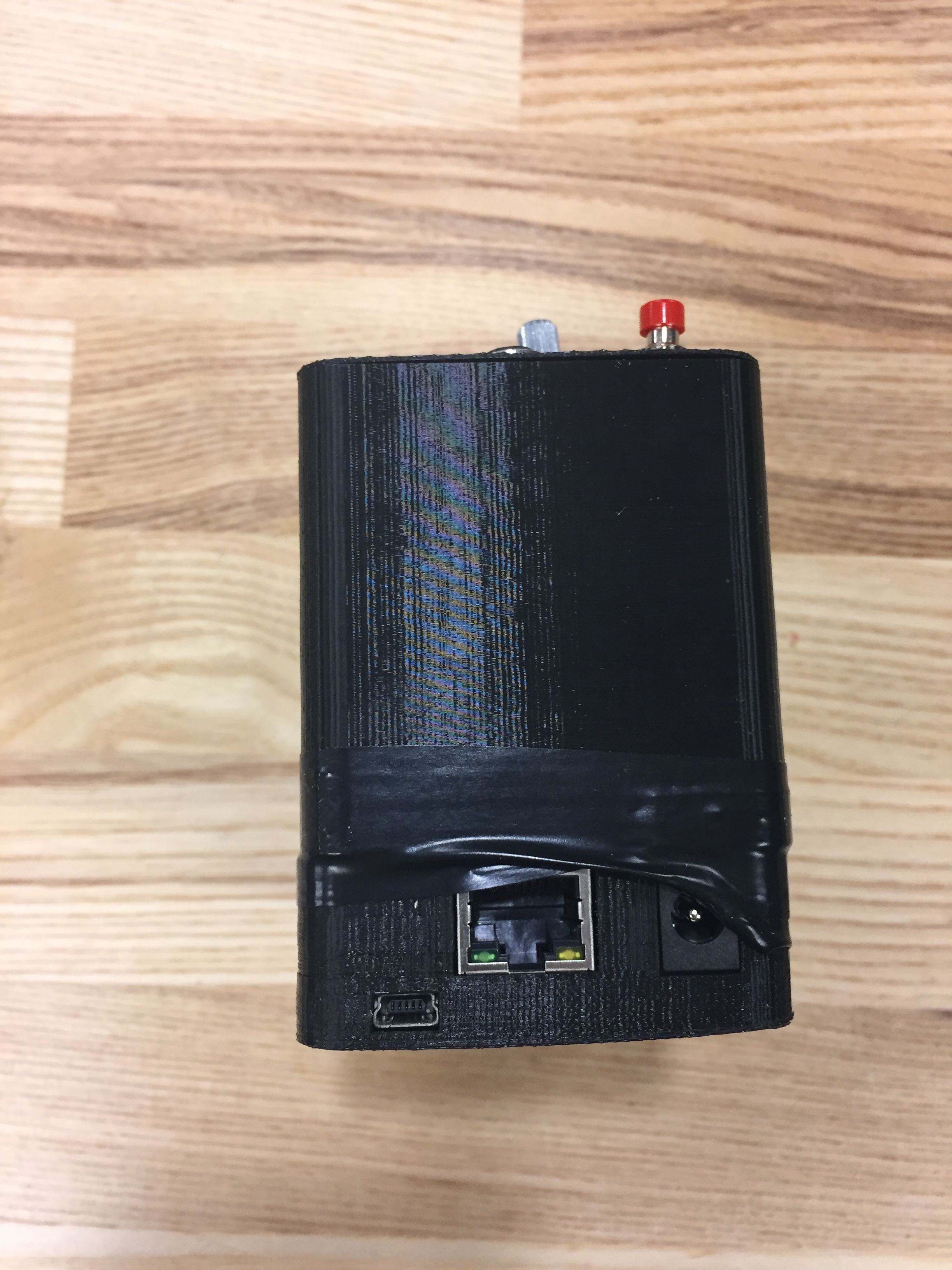
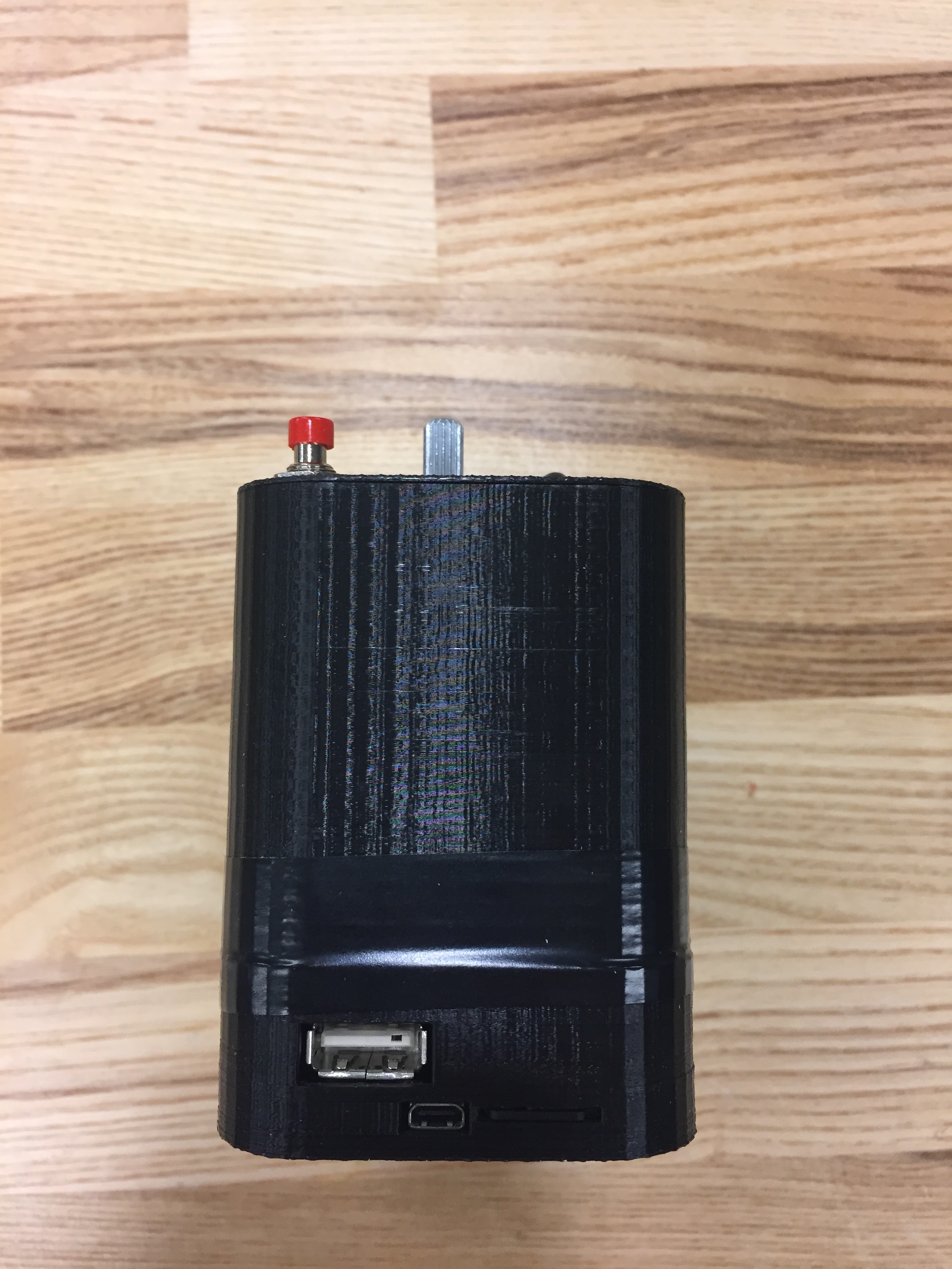
For my first project using the Bela, I 3D-printed an enclosure to fully contain the bela, and all its wiring and inputs. In order to create this case, I found an existing box for the Beaglebone Black and modified its SCAD file to make it much taller. You can download this modified SCAD file and associated files here.
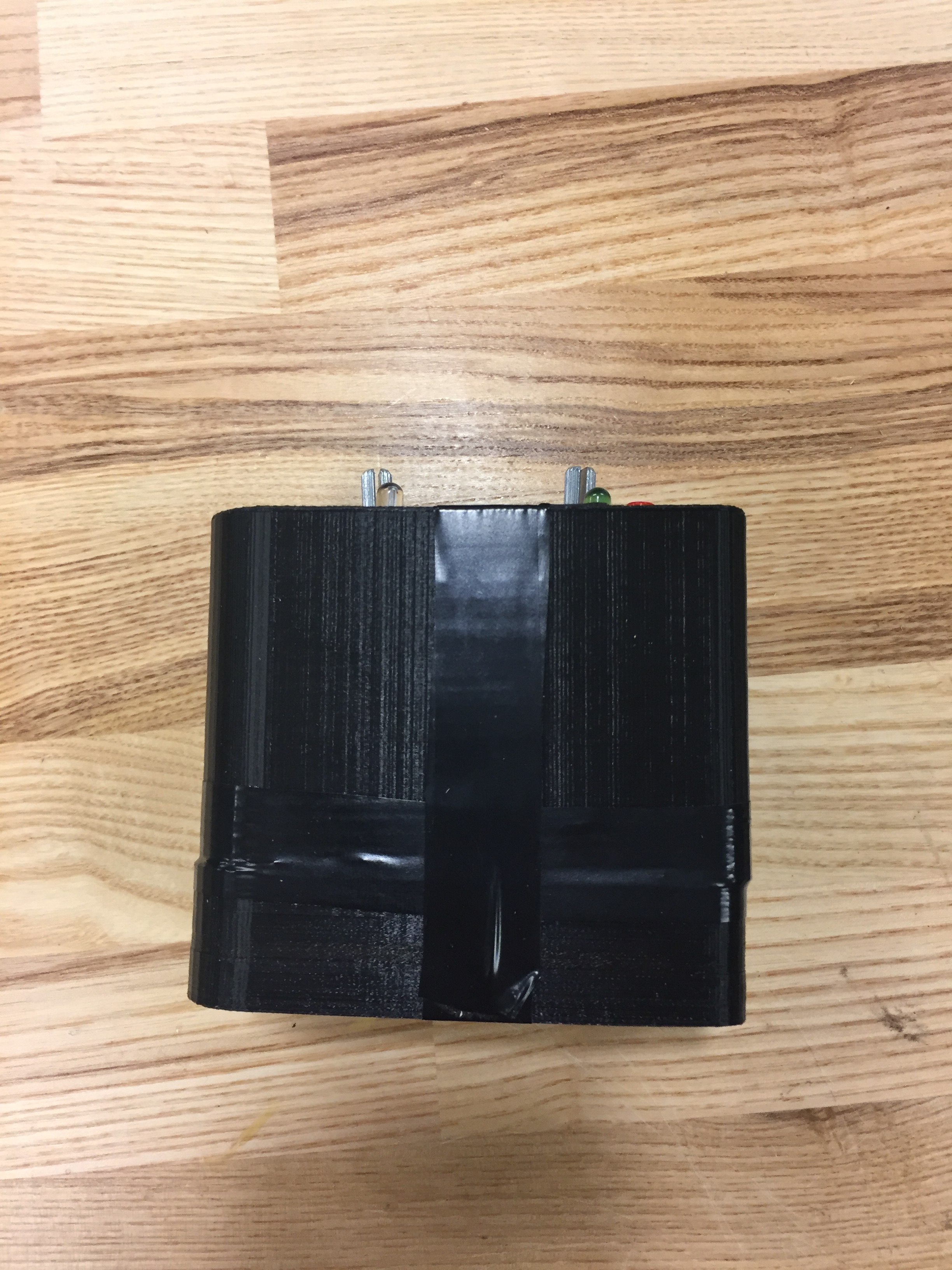
After printing the case, I realized the Bela would not fit with such high walls. After feverishly trying to stuff the Bela into the cylinder, I decided to separate the cylinder and the and bottom part of the case by sawing it off entirely.
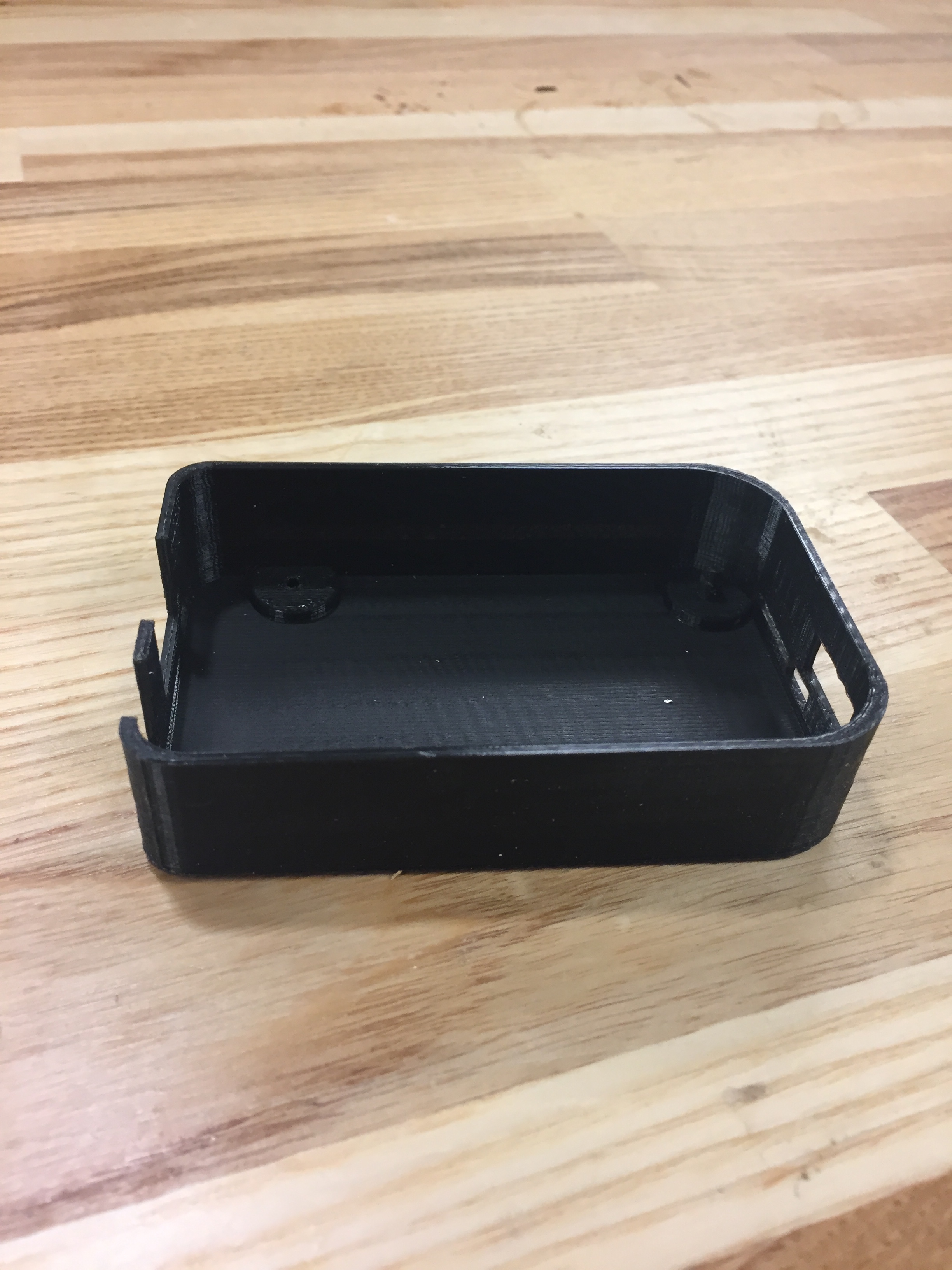
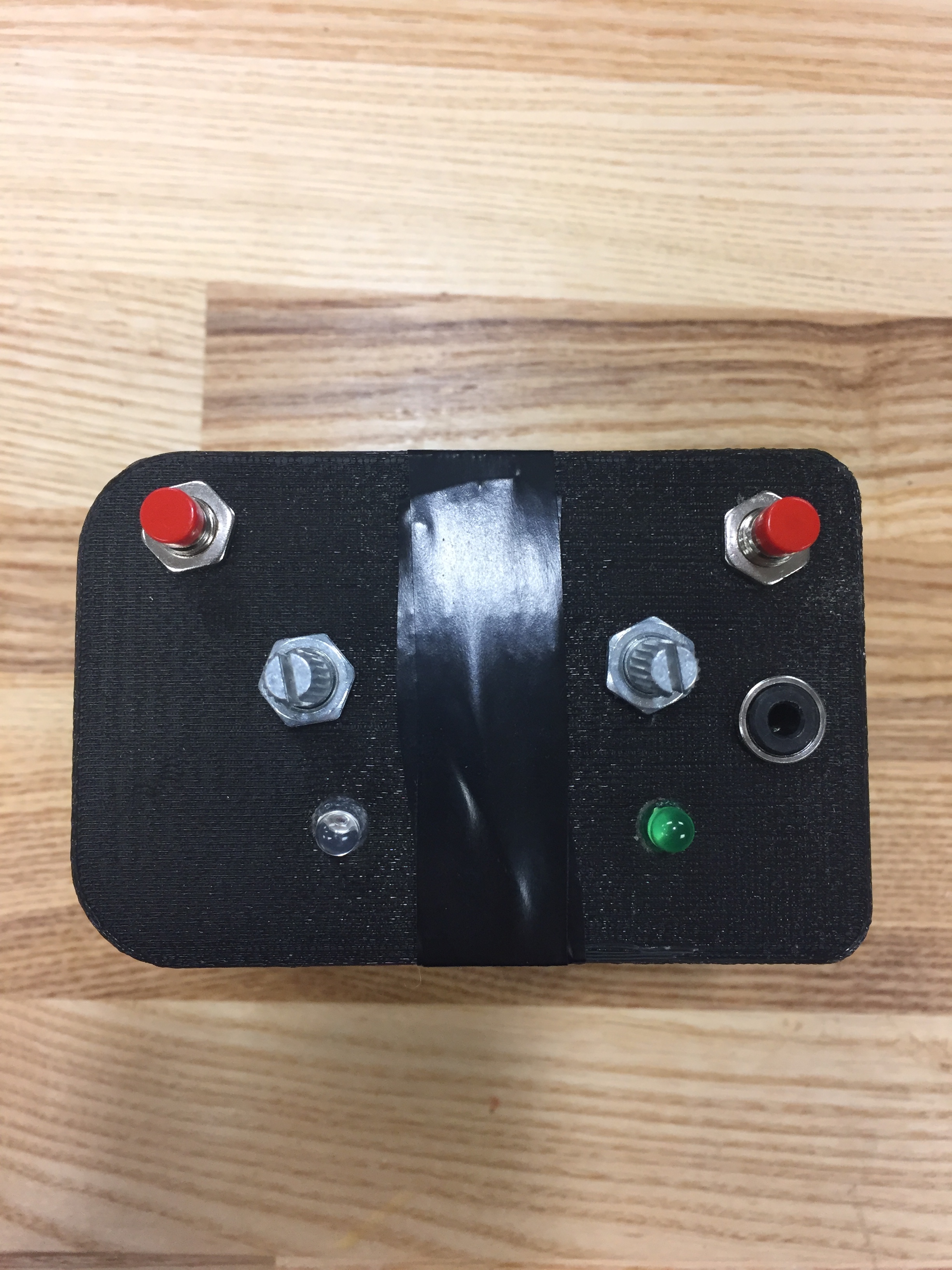
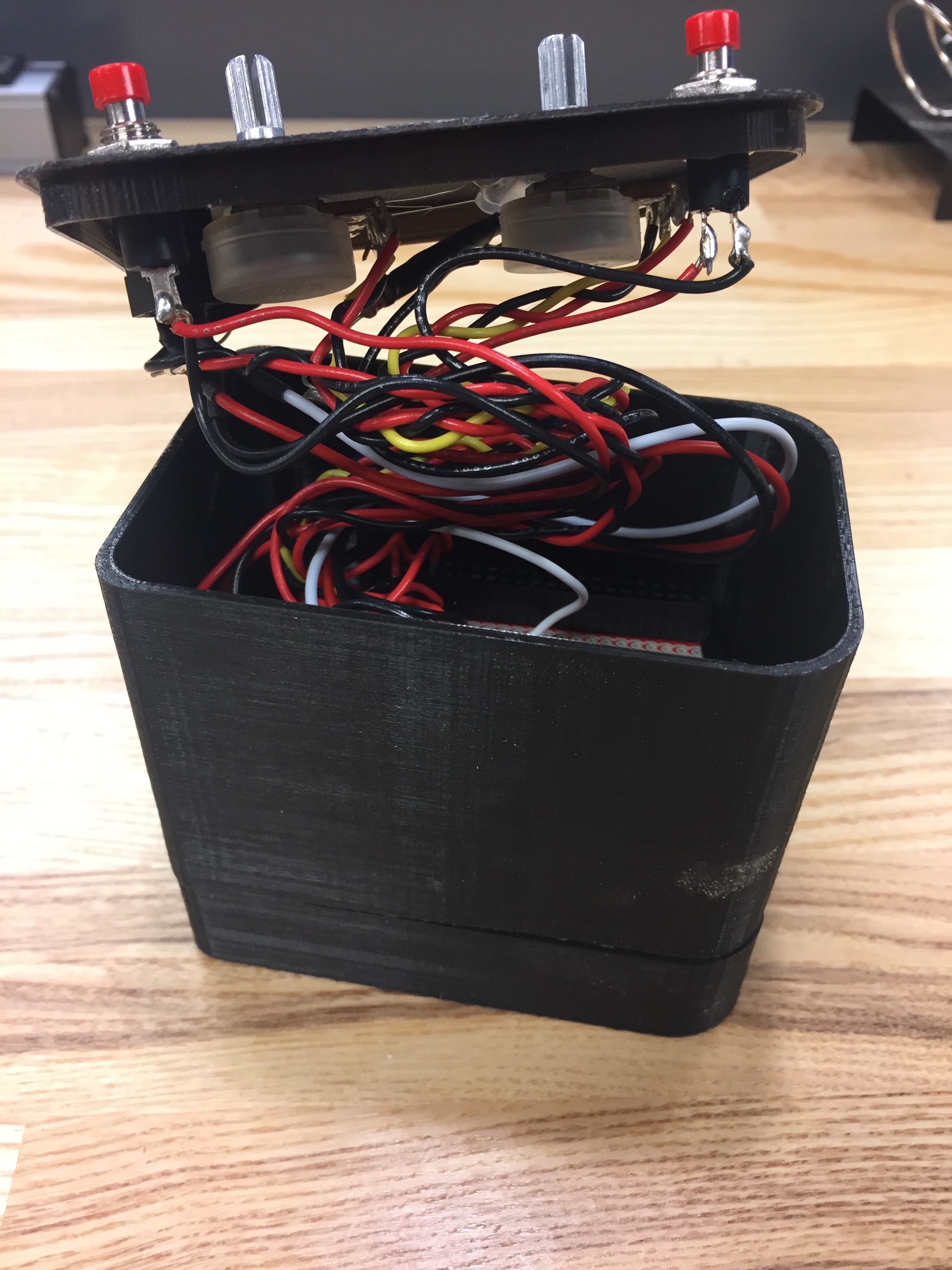
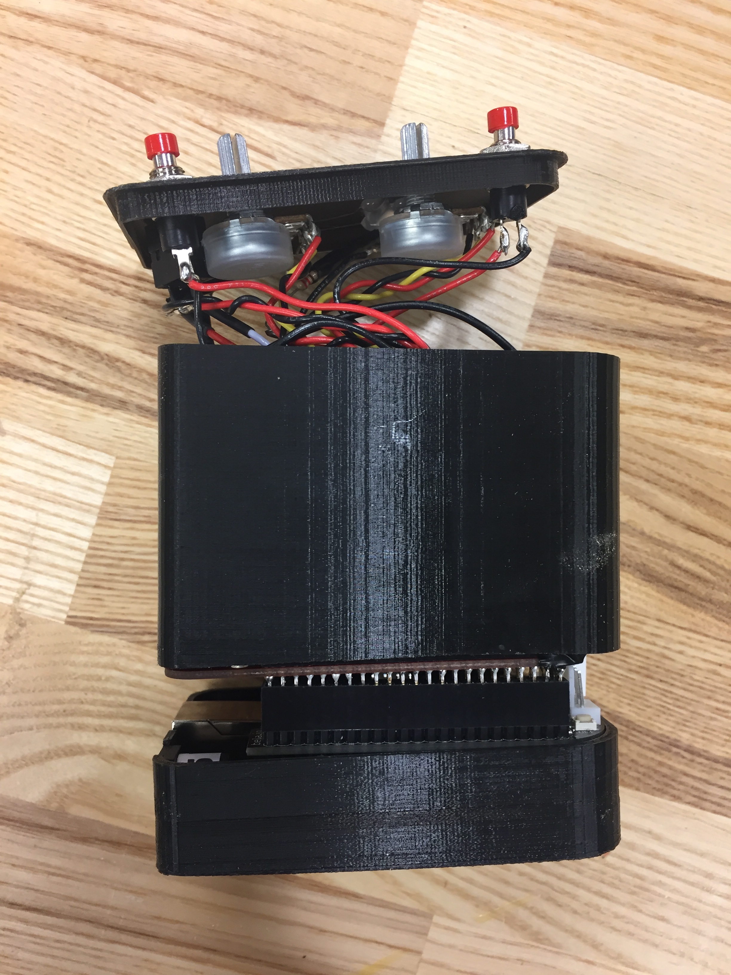
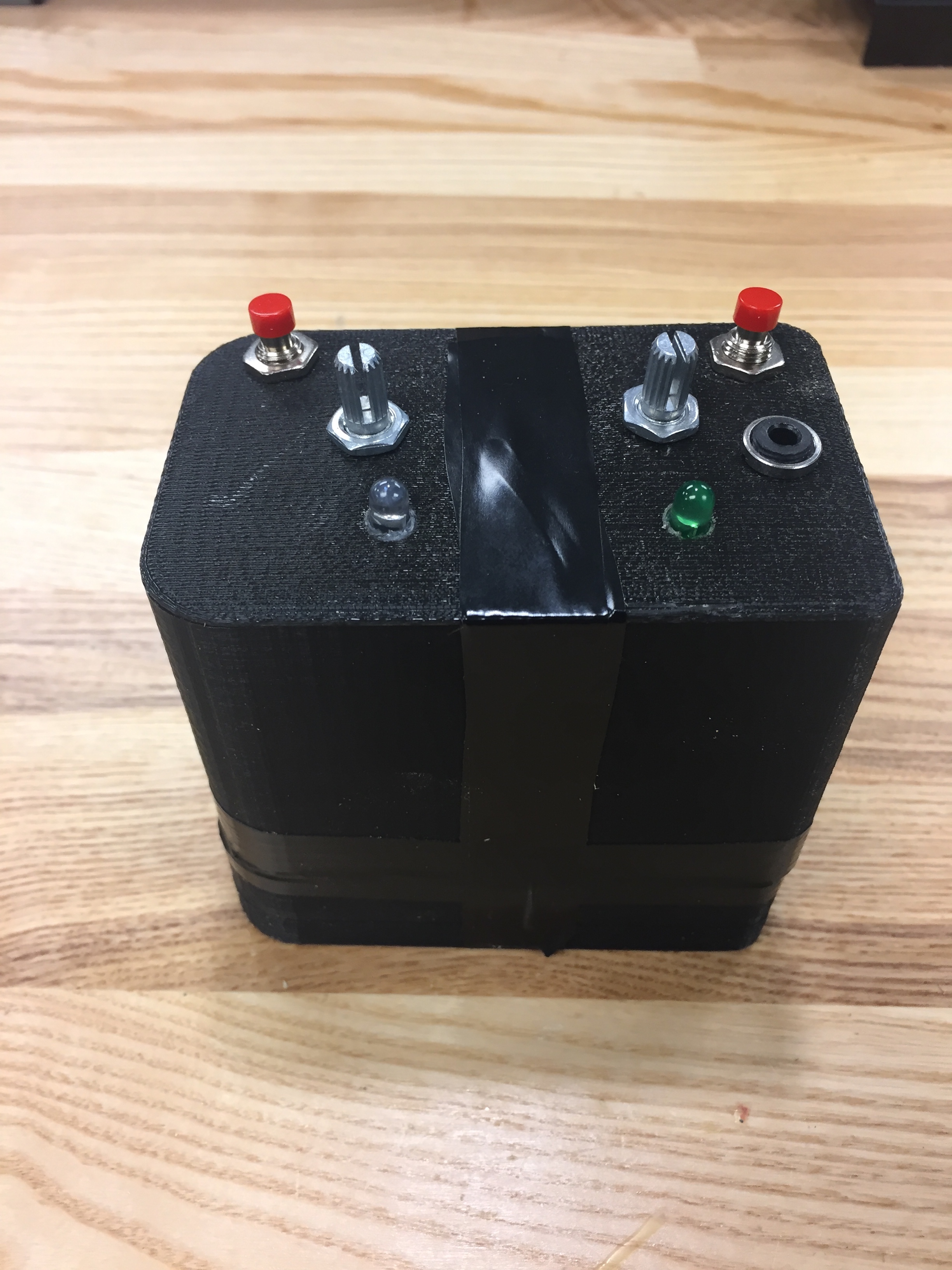
Once I had the case printed, I drill pressed some holes in the lid for access to potentiometers, buttons, LED’s and the audio jack. I then glued and screwed all the components to the lid for a sturdy fit.
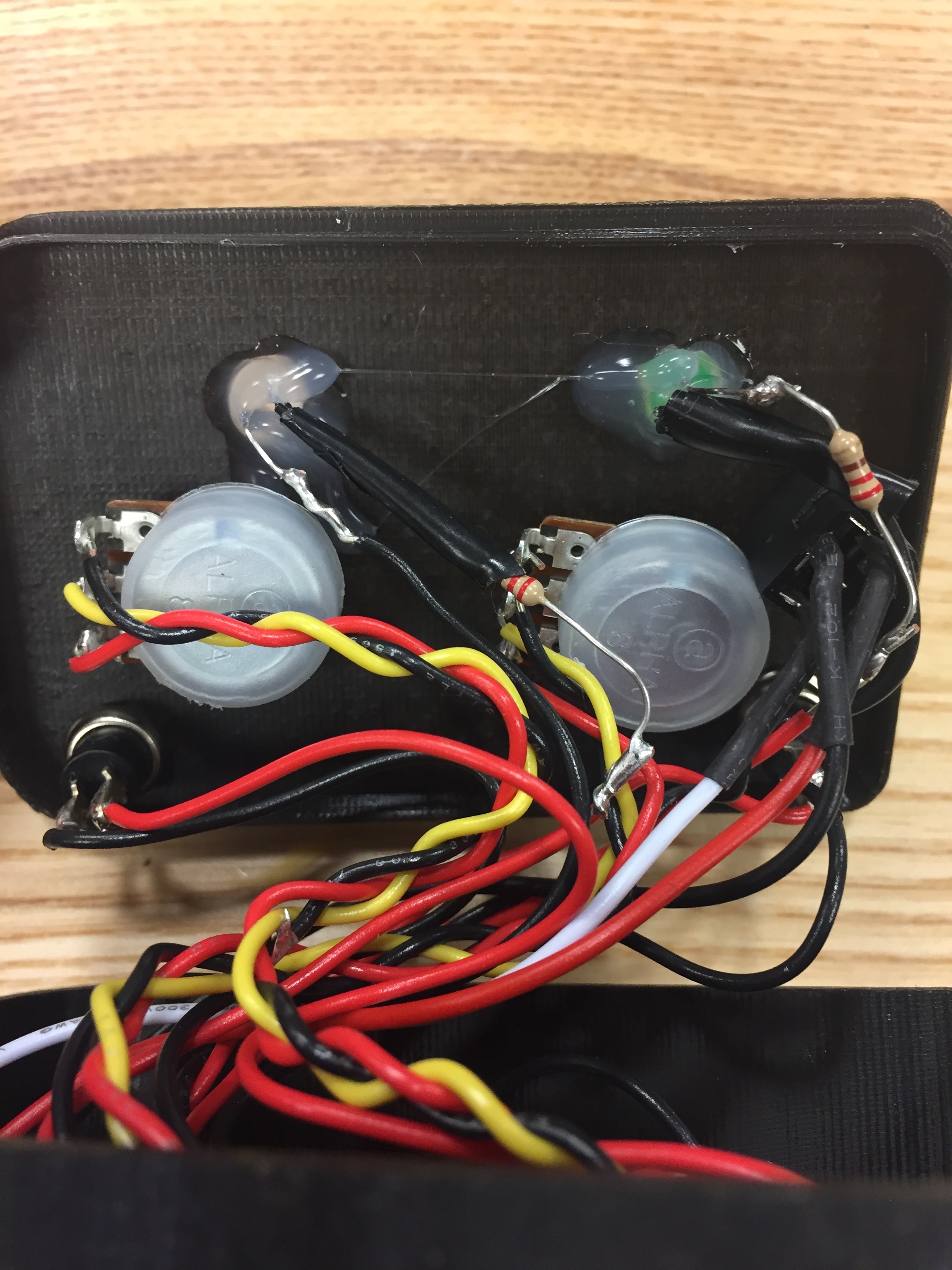
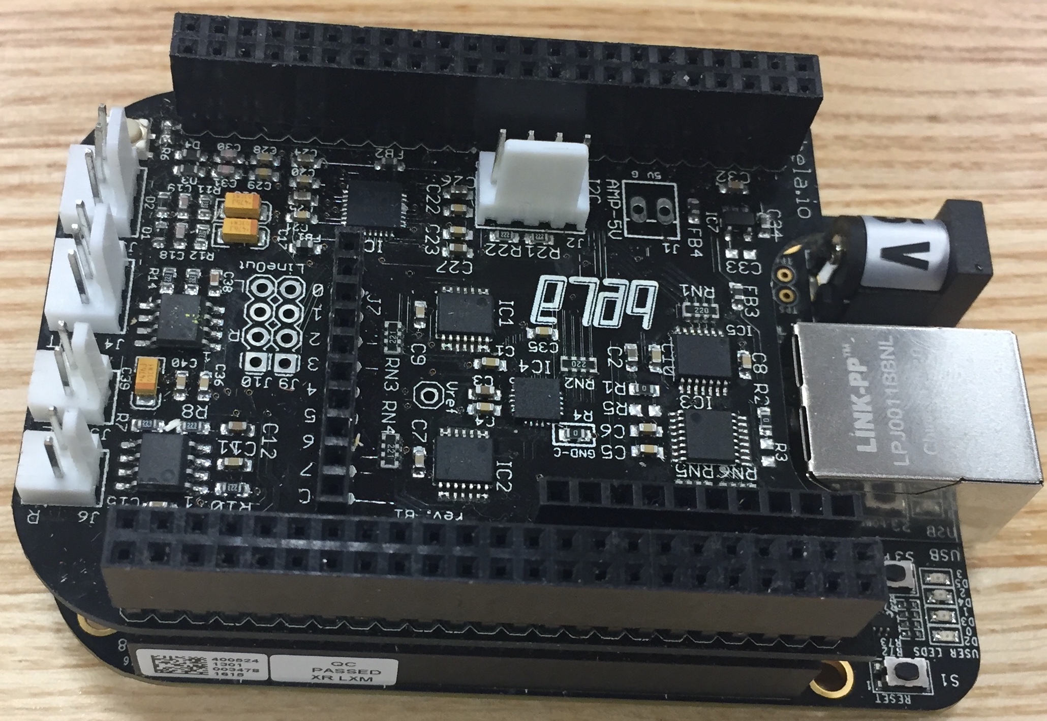
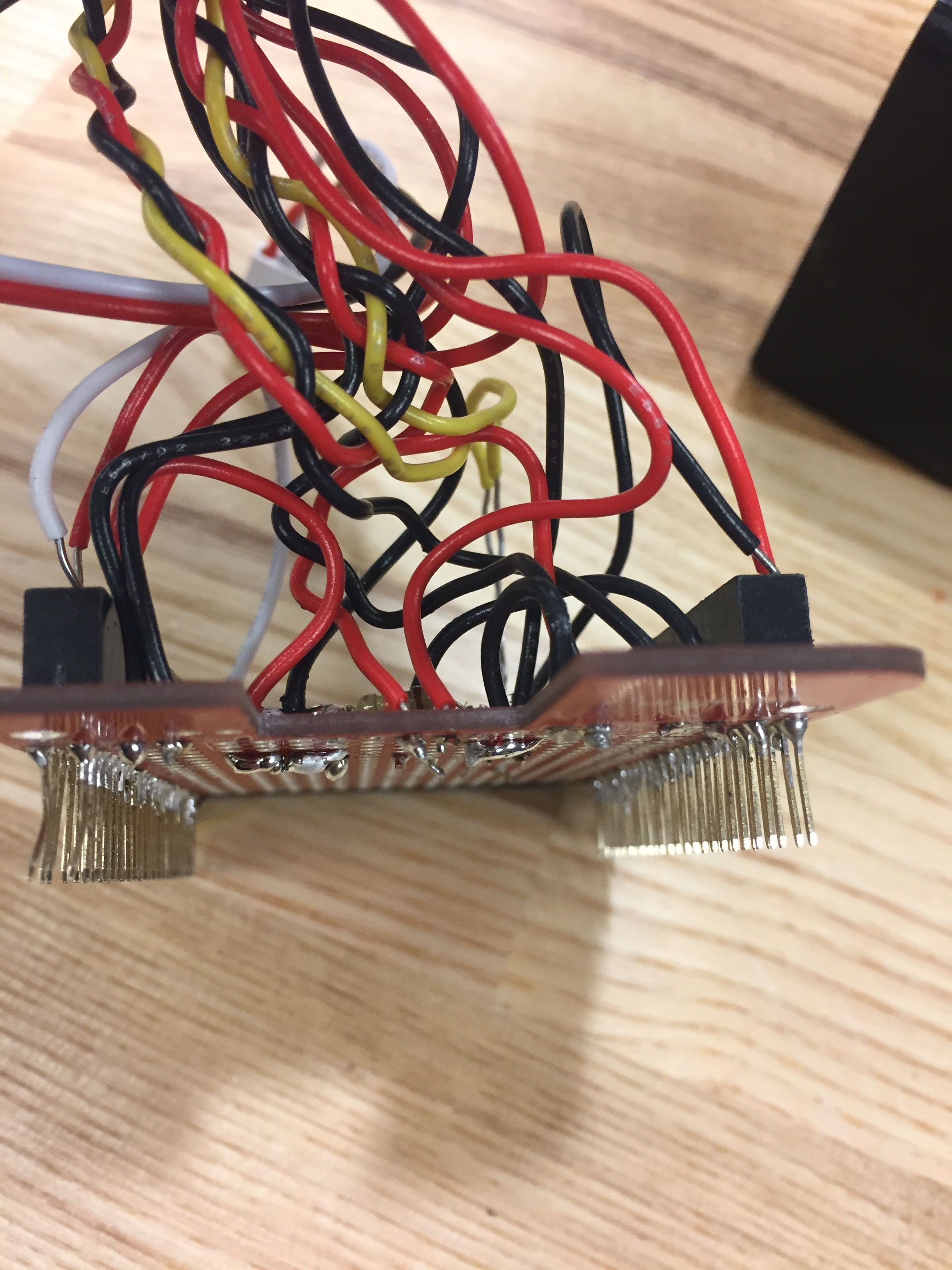
I then prepared a proto-cape for the beaglebone by soldering headers pins onto the sides and soldering the inputs onto the board. Since the analog inputs on the bela are covered by the board, I pushed the wire connected to the potentiometers through the board into the bela’s inputs.
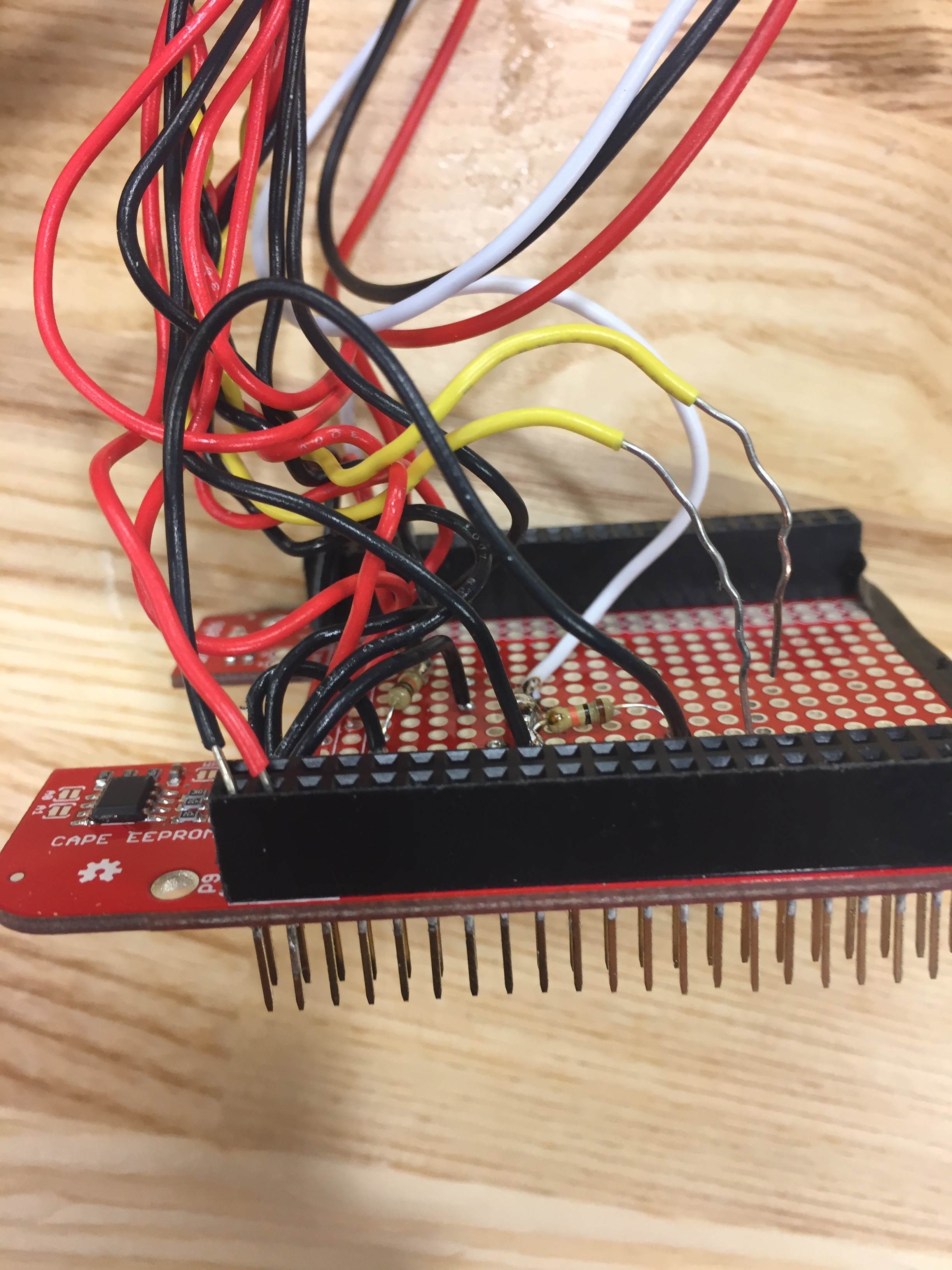
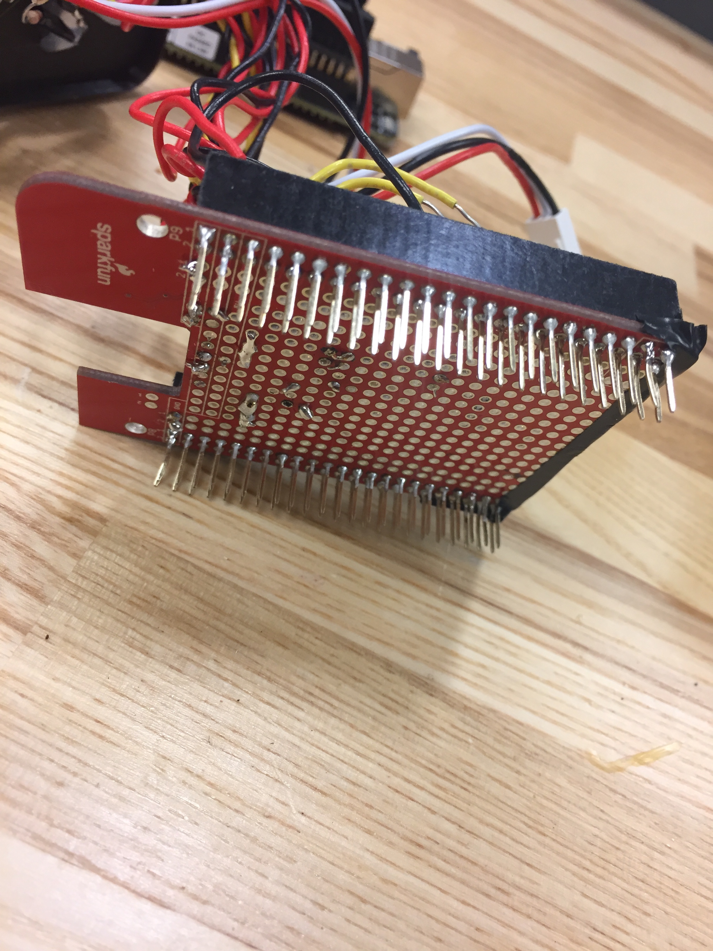
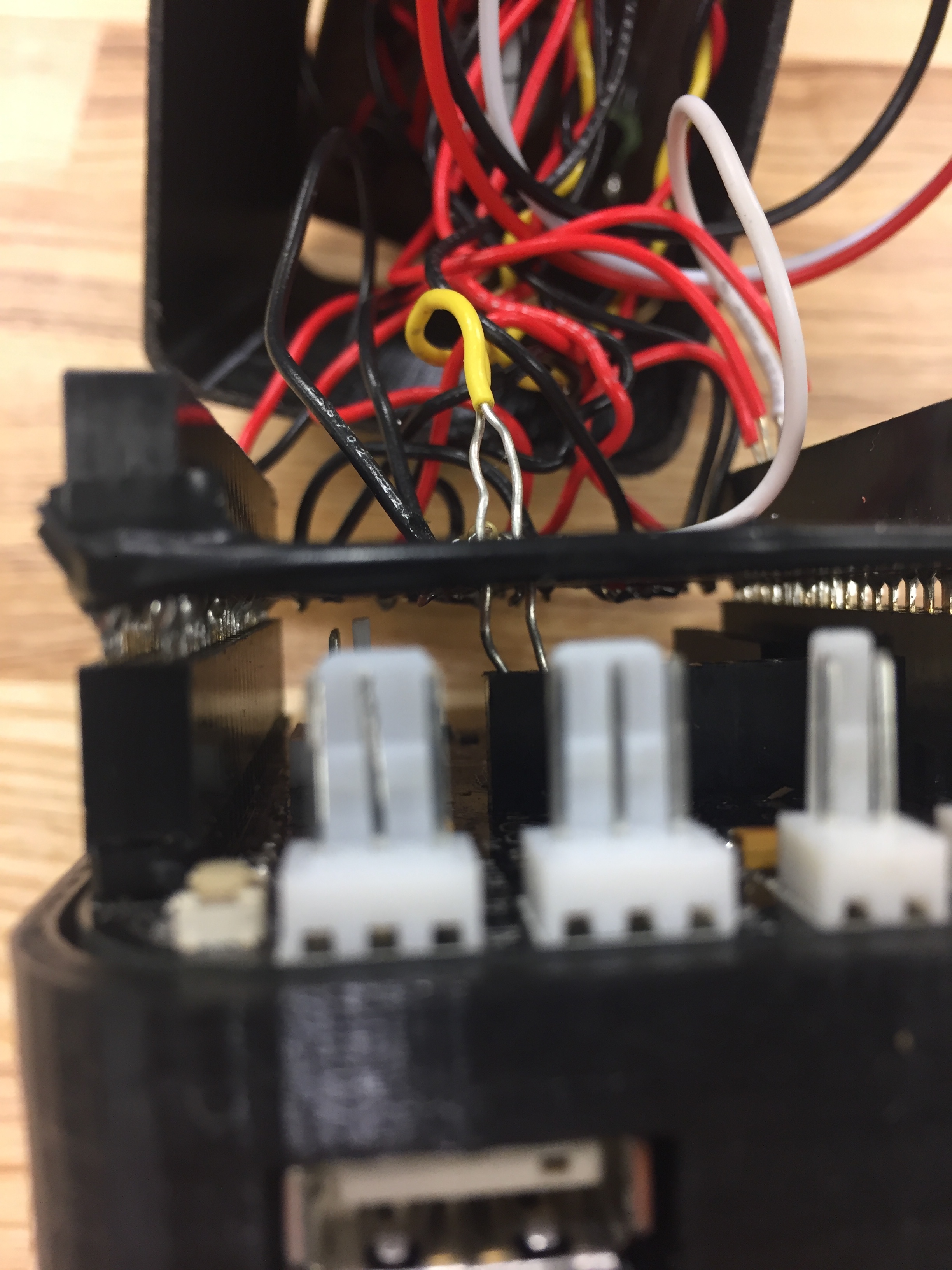
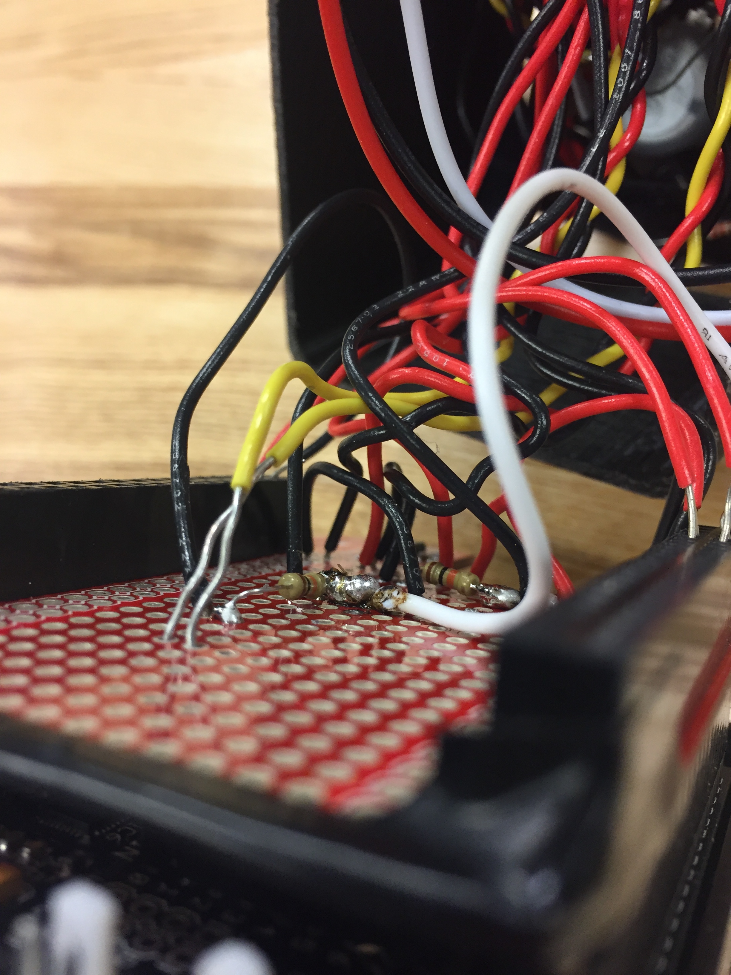
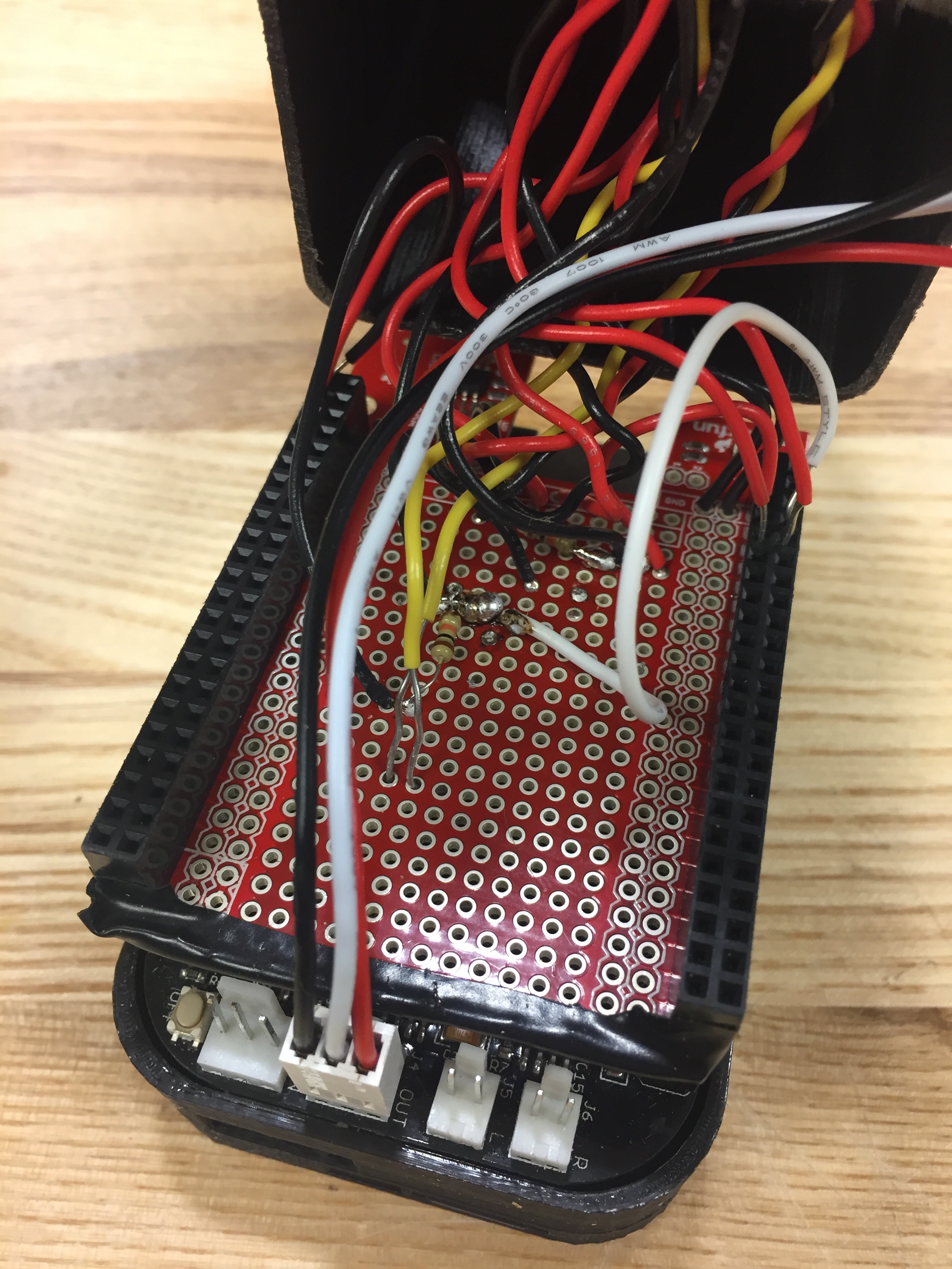
Once everything was soldered together, I attached the cape and all the inputs and shoved everything into the box.
Once everything was in the box, I started working on the Pure Data patch. I wanted something that would randomly generate tones based on the analog and digital inputs and would generate some sort of meaningful response from the LED’s. Below is a rough sketch of the patch I created:
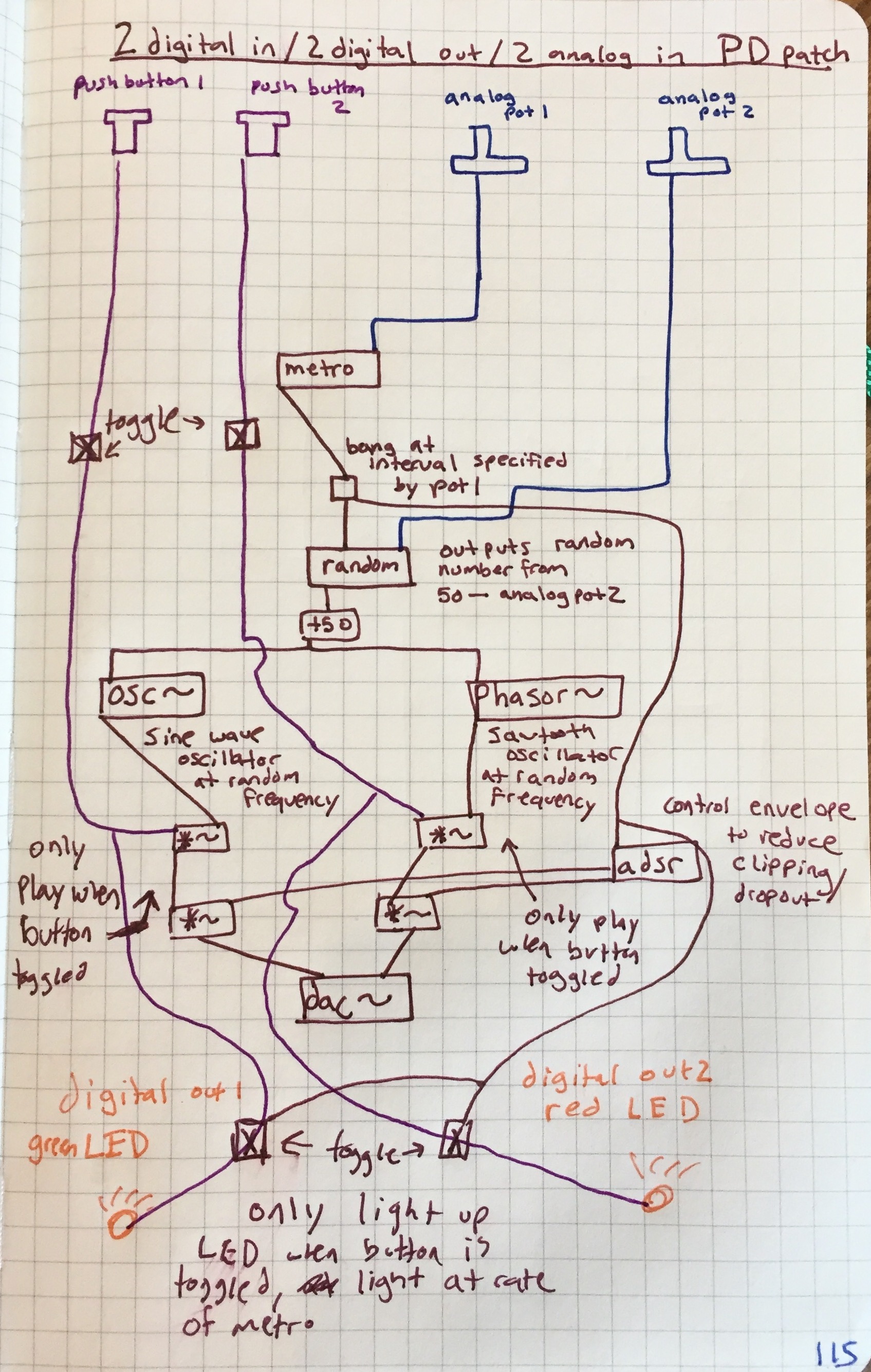
The patch has two oscillators – a sine wave in the left channel and a sawtooth in the right channel. The buttons toggle which waveform is sounding. The left potentiometer controls the speed of note generation, and the right potentiometer controls the randomness (what range of frequencies can be generated from 50-800hz).
You can download the PD patch here.
Video performance coming soon!